 EN
EN TH
TH VN
VN JP
JP CN
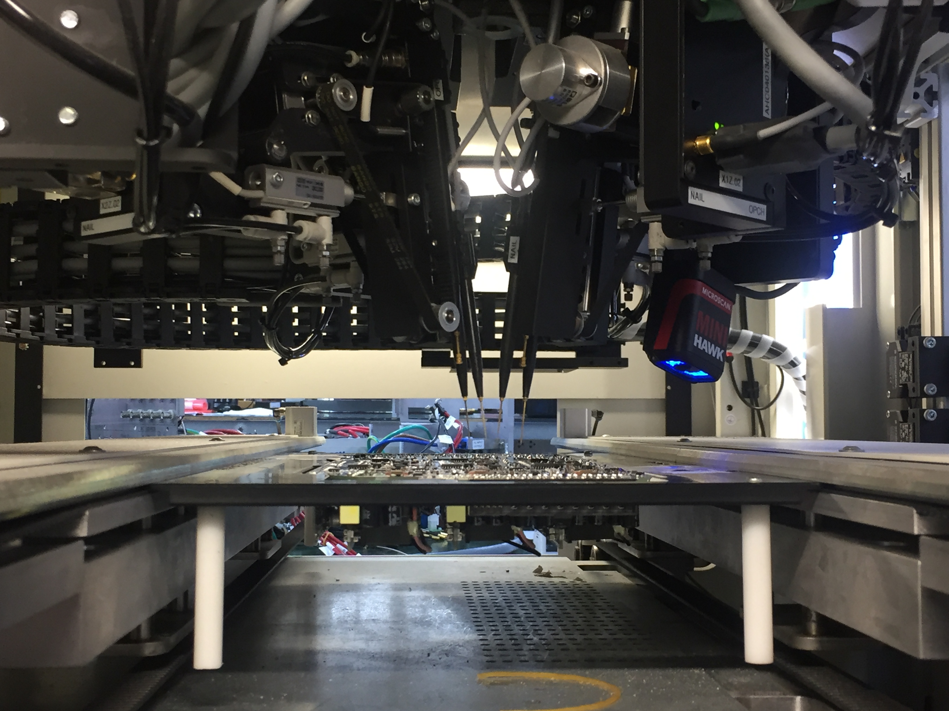
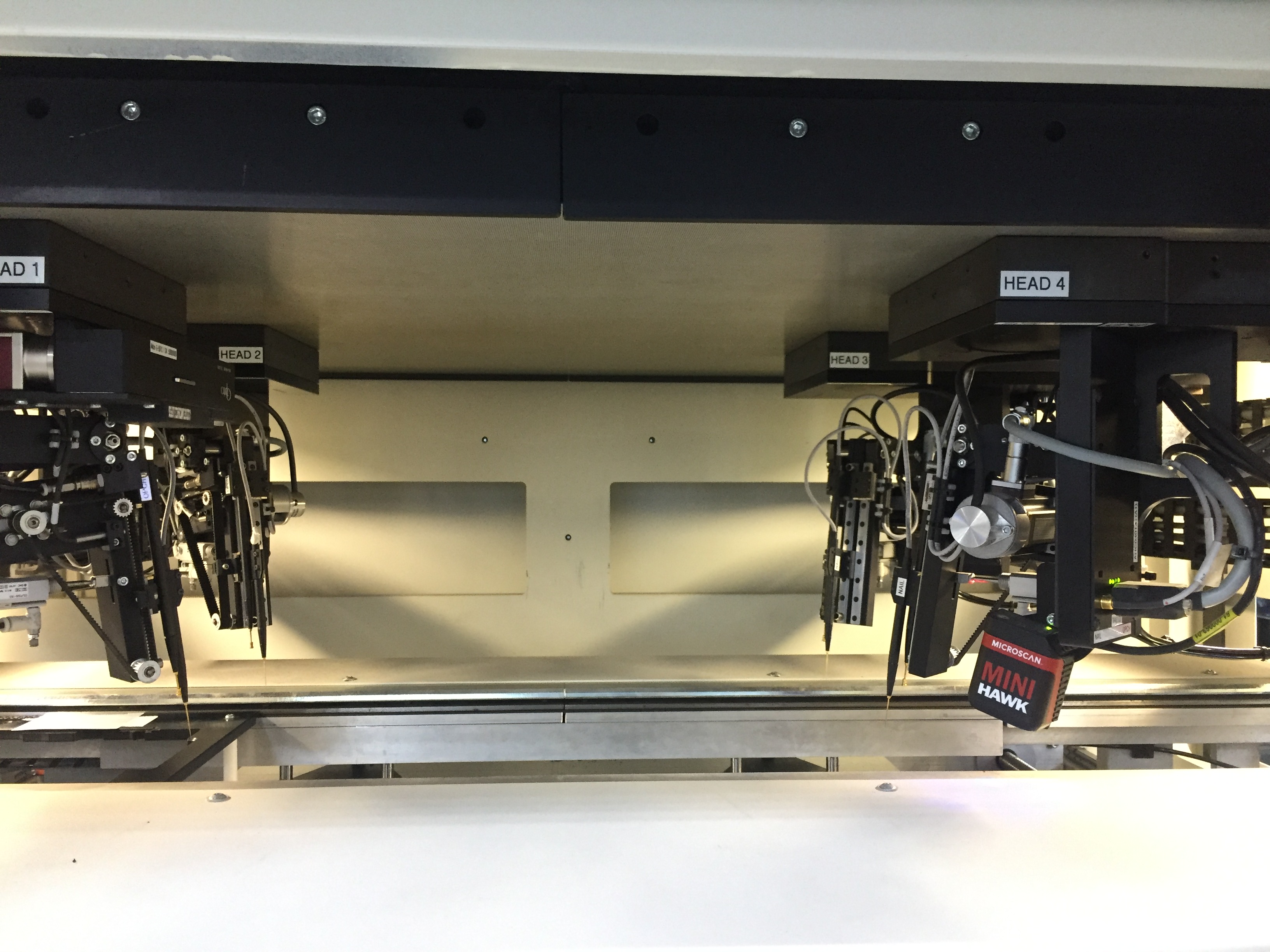
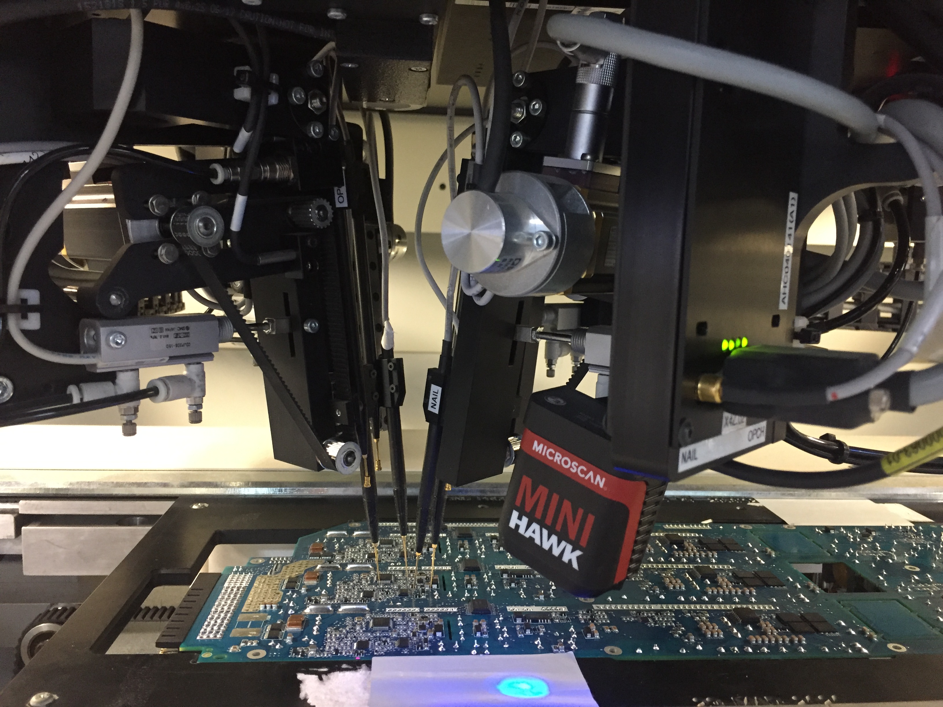
CNMTS 505 Flying Probe
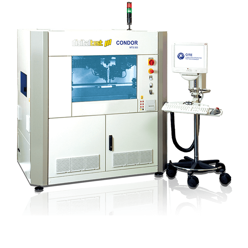
Our Condor MTS 505 flying probe tester requires no fixture and is therefore ideal not only for traditional production, but also for prototyping and low-volume production. Thanks to the four movable test heads it offers high adaptation depth and test coverage. The optional use of fixed test pins on the underside of the test object means you can also shorten the test time while increasing the test coverage. The Flying Probe test system is equipped with a digital color camera (CMOS) with GigE Vision interface to accurately determine the position of the probe and device under test (DUT). It is attached to one of the four test heads and contains optics, as well as lighting.
DETAILS
Front-loader |
In-Line |
||||||||||||||||||||||||||||
| The board to be tested is manually placed in the tester using a front pull-out with two-handed locking. The bed rails feature adjustable tabs for automatically fixing the board. Magnetic fixing pins, support pins etc. can also be positioned on the base plate of the pull-out. | Our in-line tester can be fully integrated into your production line. The circuit board moves automatically over the conveyor inside the tester via an in- and outfeed. The module is clamped up towards the top for testing, so that the PCB thickness makes no difference for contacting. SMEMA-compatible connections are available for pre-heat and post-cool modules in your production line. | ||||||||||||||||||||||||||||
Features |
Features |
||||||||||||||||||||||||||||
|
|


Software
Our range of PCB test software covers your requirements in the entire production process: from preparation of CAD files to test program generation and quality assurance.
We offer software for non-destructive reconstruction of CAD data, professional CAD/CAM software, the system software for our test systems, as well as paperless repair software. Except for our CITE system and Digitizer software, you can use our software packages for any test system.

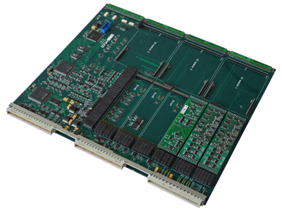
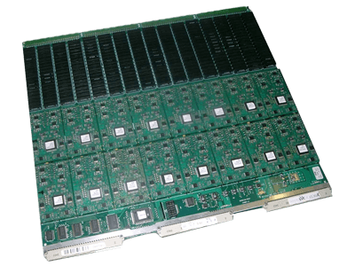
Analog Measurement Unit – heart of the system
The AMU05 (Analog Measurement Unit 05) is the core of all our test systems. It ensures that all the measurements are performed faster, more accurately and with even greater stability.
Improves the quality of your test programs
When it comes to the test coverage of a program in the analog ICT, the question is not only whether there is a test for every component and if it was performed, but also whether the test would in fact recognize a fault.
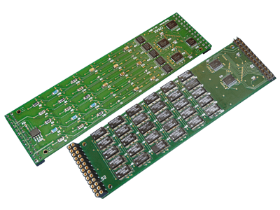
Switching matrix
The Analog Signal Switch Unit serves as a 6-bus interconnect for 128 pins each to the Analog Measurement Unit (AMU05) for the In-Circuit test.
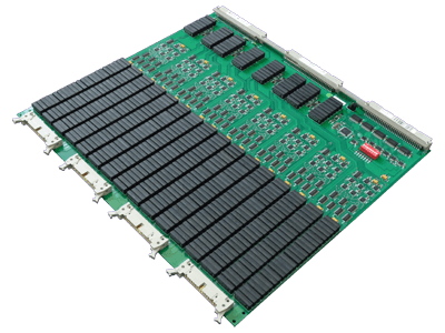
128-Pin hybrid driver/sensor module
The HYB04 enables comprehensive analog as well as digital driver- and sensor-functions. It has 128 non-multiplexed hybrid pins per module.
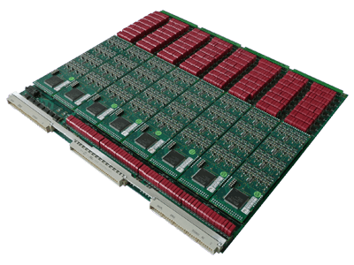
64-pin hybrid driver/sensor module
Our HYB03 enables comprehensive analog as well as digital driver- and sensor-functions. It has 64 non-multiplexed hybrid pins per module.
https://www.digitaltest.com/en/
